During my spare time I like to play with home automation, internet of things and hardware stuff. The latter is interesting. I really don’t know anything about hardware or electronics, but I do like to play with it. One of the things I have built is a weather station on solar power. Next to building stuff like that, I run home assistant to automate lots of things within my house. Not so much because its useful, but because it’s fun.
Another project 😊
We recently started our new company Zolder. While we were in the process of developing our identity, I got an idea for another project: building a Zolder logo with WS2812B ledstrips behind it, to give it some cool effects.
Designing the logo
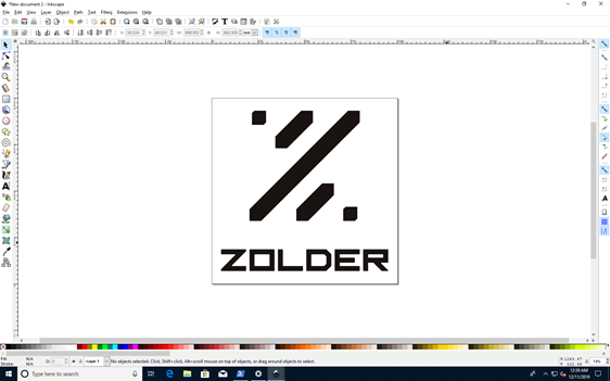
Just prior to that I got familiar with laser cutting company Laserbeest. Their products were great, so I decided to ask the same company to create our logo as well. We received the EPS files from our designer, I started by playing around with the files and prepare them for Laserbeest. I wanted to use a 1000x1000mm MDF as backplate. I modified the EPS file so the logo would fit on the backplate. The result looks like this:
The cool thing was: after sending Laserbeest above EPS file, they modified the source file for the laser machine, to perfectly print our logo. They also included a template that can be used to make sure all parts are positioned in the correct offset from each other:
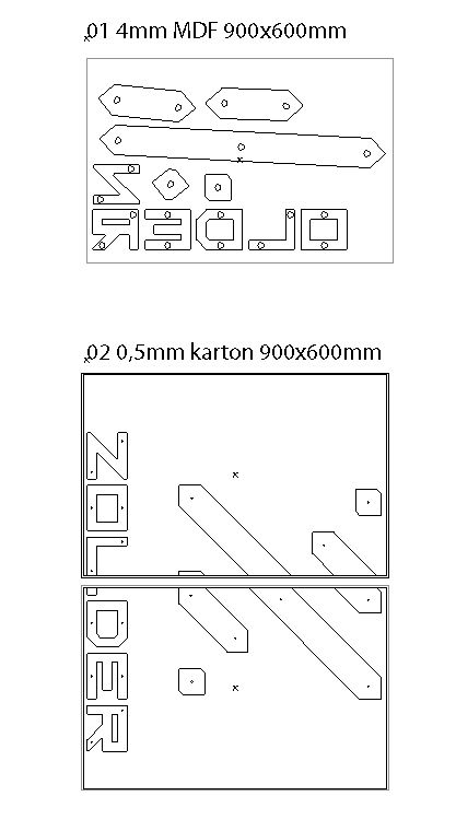
After retrieving above image I gave them the assignment to print our logo. Than it was time to wait for the results:

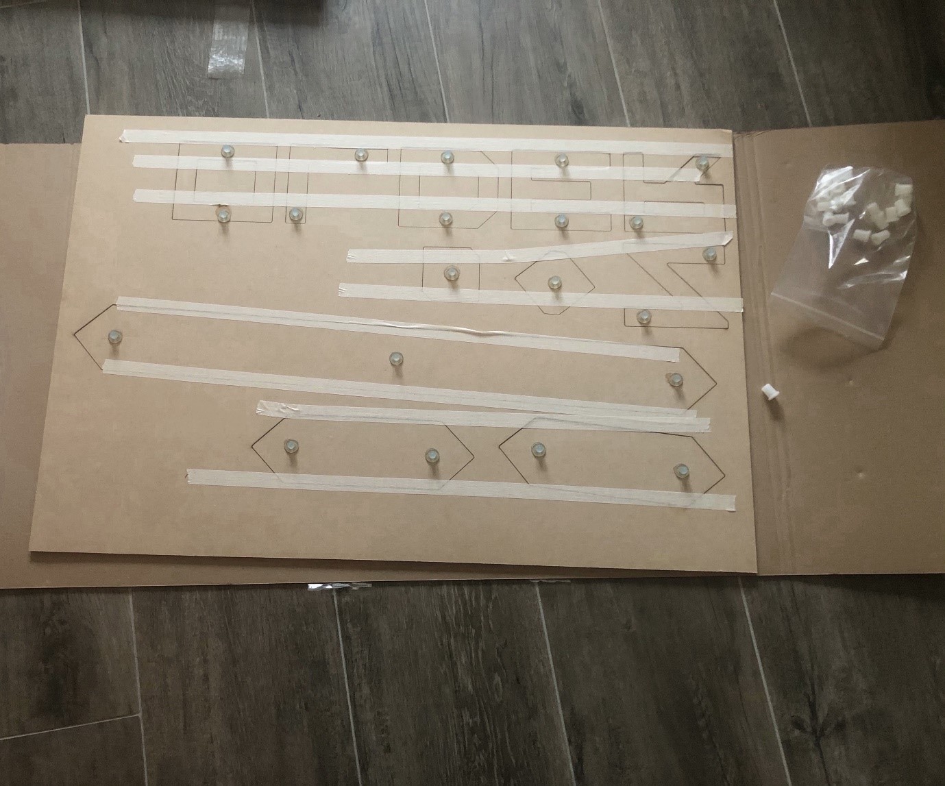
After a few days I received the logo. Even the placeholders were already present, which surprised me at that time. The result looked great, so I started building a device to get the led strips working.
Building the microcontroller + ledstrip device
I figured out the best setup along the way. Using materials that were already laying around in my home, but selected them based on best fit for this project. In the end these were the components I used:
| Component | Links |
| 8-channel Bi-directional Logic Level Converter – TXB0108 [ADA-395] | Link |
| Draad – Solide Kern – 7.5m – 22AWG – Rood [KW-2364] | Link |
| Draad – Solide Kern – 7.5m – 22AWG – Zwart [KW-2366] | Link |
| Draad – Solide Kern – 7.5m – 22AWG – Wit [KW-2367] | Link |
| 2.1mm DC barrel jack – Breadboard compatible [KW-1602] | Link |
| Adafruit Perma-Proto – Half-size [ADA-1609] | Link |
| Weerstand 470 Ohm – 1/4 watt – 5% – 10 stuks [KW-805] | Link |
| Universal Power Supply – 3-12V 1A – 6 plugs [KW-1554] | Link |
| Adafruit HUZZAH ESP8266 Breakout [ADA-2471] | Link |
| WS2812B 60 black PCB IP67 3m | Link |
| 1000 uF Capacitor | Link |
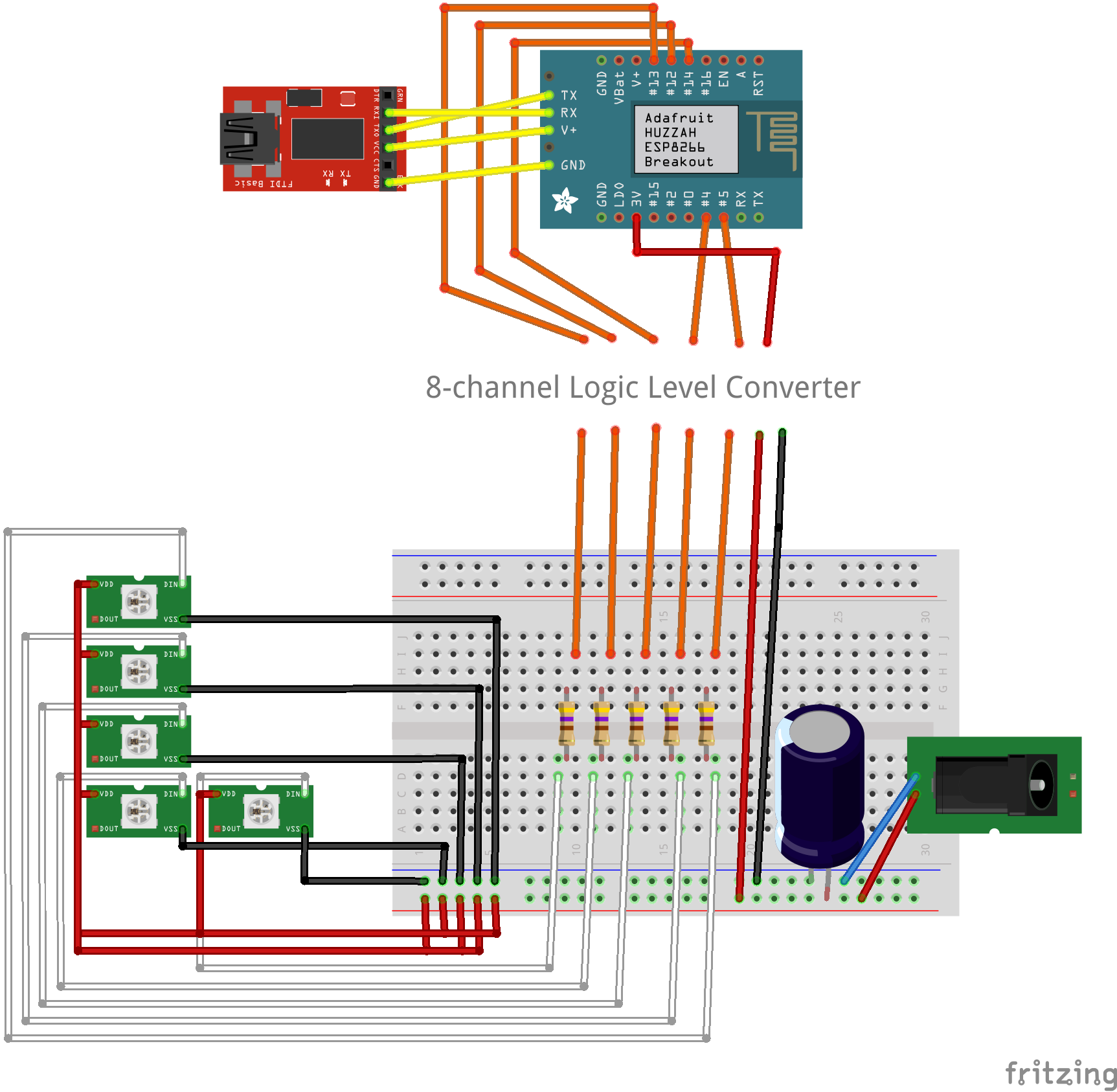
Above components were connected to each other according to the scheme below:
Microcontroller software
On the internet I found multiple libraries to control the led strip from a ESP8266 microcontroller. A commonly seen library was FastLED. FastLED was also great for this project, as it easily allows mirroring to multiple led strips. As my setup contained 5 separate led strips, I decided to go for this library.
The next step was to find appropriate software for this project. Why build the software myself, if other people already did that? Also, I am quite a noob in the C-language, which is used on ESP8266 microcontrollers.
The first project I came across was a FastLED webserver for the ESP8266. After some small modifications, adding multiple led strips, I got this code working in my setup. Here is a photo from the led strips working the first time:
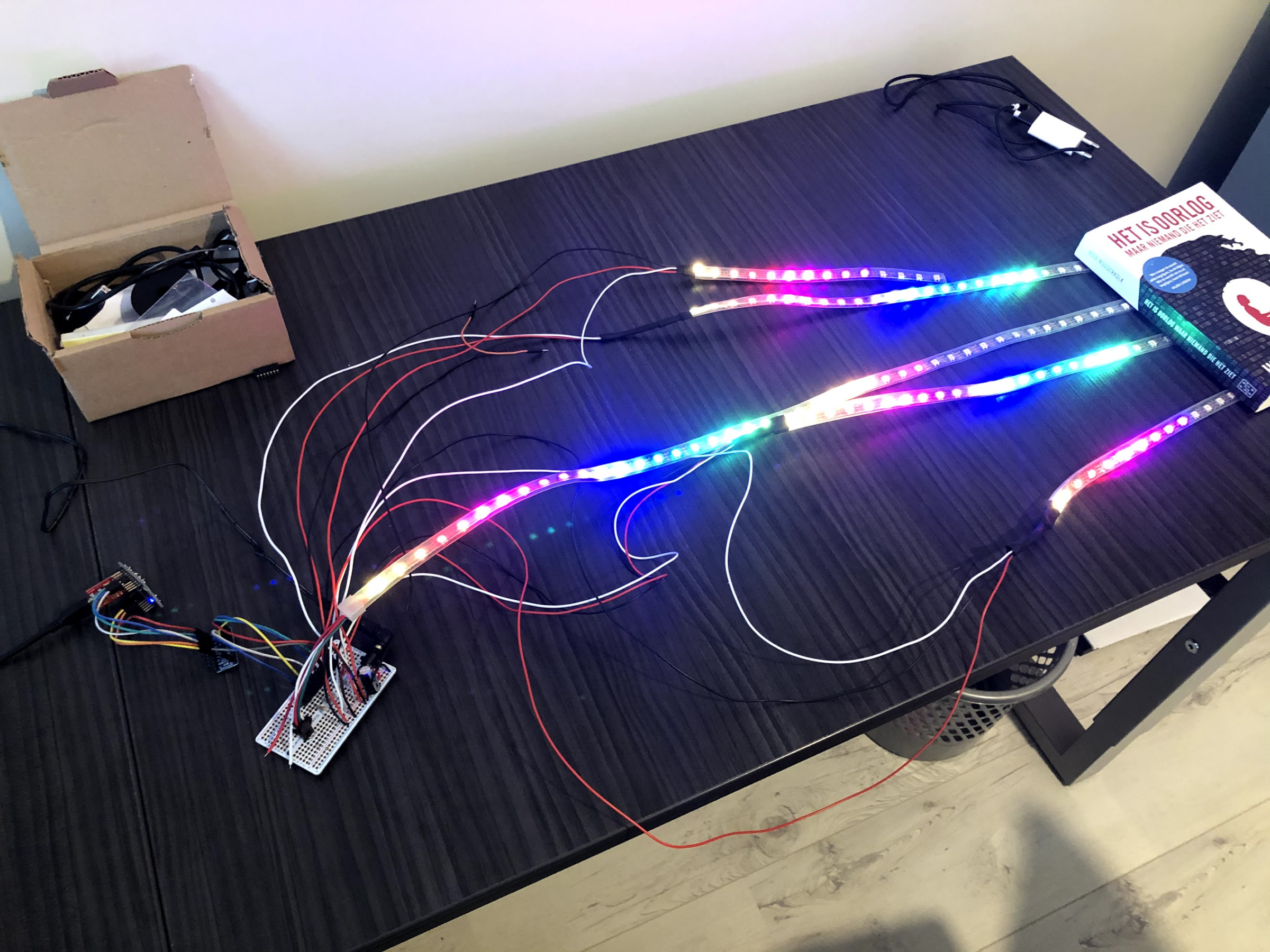
Later on I came across another project which was much more suitable: a FastLED microcontroller communicating over MQTT that was Home Assistant compatible. This perfectly fitted my needs, as I am a Home Assistant user and at that time I was also playing with zigbee2mqtt. I had the MQTT server already running and connected to Home Assistant, so I just had to flash the microcontroller and add the strip to the existing MQTT server 😊. Connecting the logo to home assistant had many advantages. It allows me to connect all the existing sensors / information in my smart home to the logo. For example: if motion is detected in my office, the logo turns on. If there is no motion for 5 minutes, it automatically turns off the logo.
Painting the logo
The microcontroller and the led strip were working. The next step was painting the logo. I decided to use black for the logo itself, and white for the black plate. TIL: MDF needs a lot of primer 😊. The result:
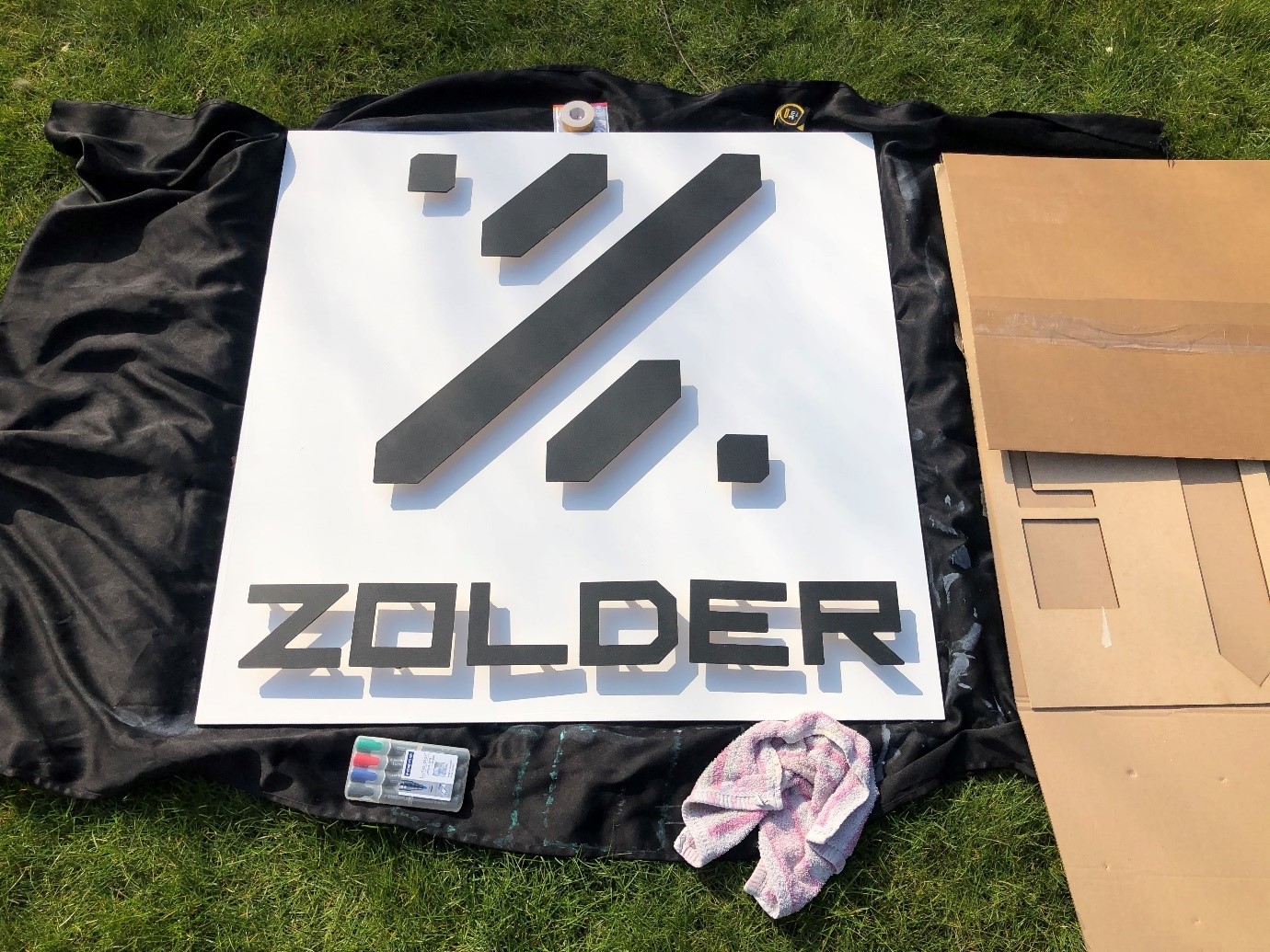
Installing the led strip
The last step was to install the microcontroller and led strip on the board. The challenge was not to break the led strip connection during installation (of course, in the end one connection broke nonetheless 😊). However, after creating the required holes the board looked like this:
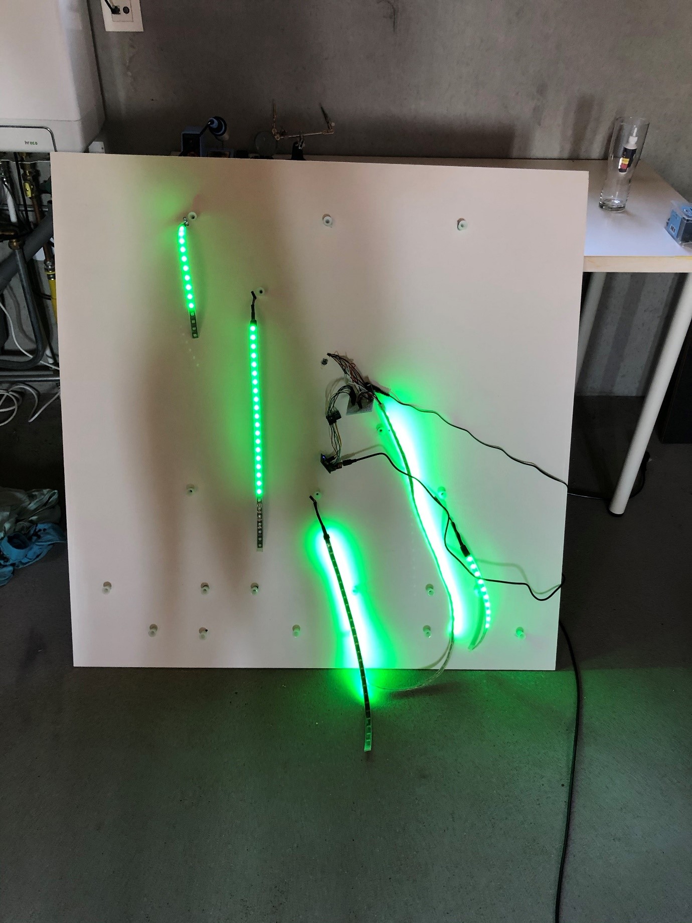
After putting everything in place, the end result looks like this:
[youtube https://www.youtube.com/watch?v=mIOYee8YWFQ]
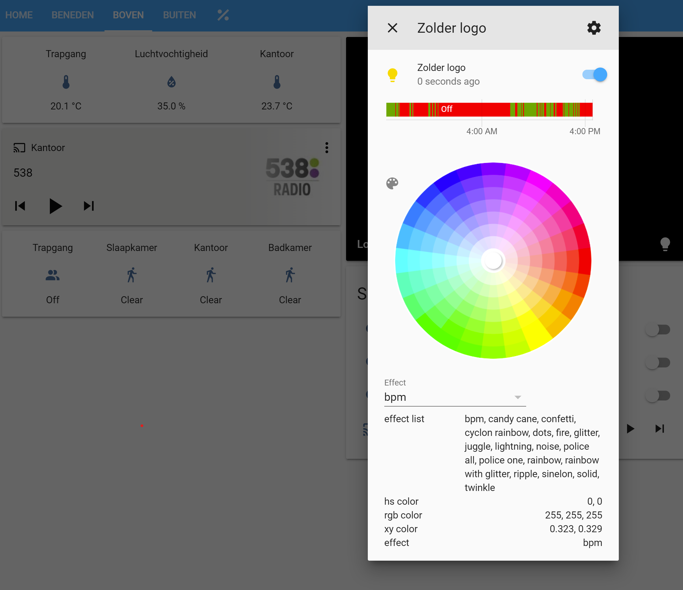
At recording time of above video I was still using the FastLED webserver. Flashing the MQTT firmware and configuring Home Assistant made the logo available and controllable within Home Assistant:
End of the project 😊. Learned a lot. And had a lot of fun.
